
Relays
Voltage fluctuations and unstable power supplies damage sensitive equipment and shorten the operational life of motors, compressors and controls in critical installations. TAXNELE Voltage Relays provide automatic protection by monitoring supply quality and disconnecting loads when voltages drift outside safe operating ranges. Order at the official store today and receive the best price on automatic protection relays engineered for residential, commercial and industrial power systems.
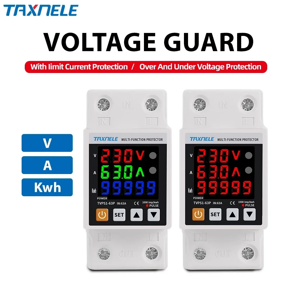
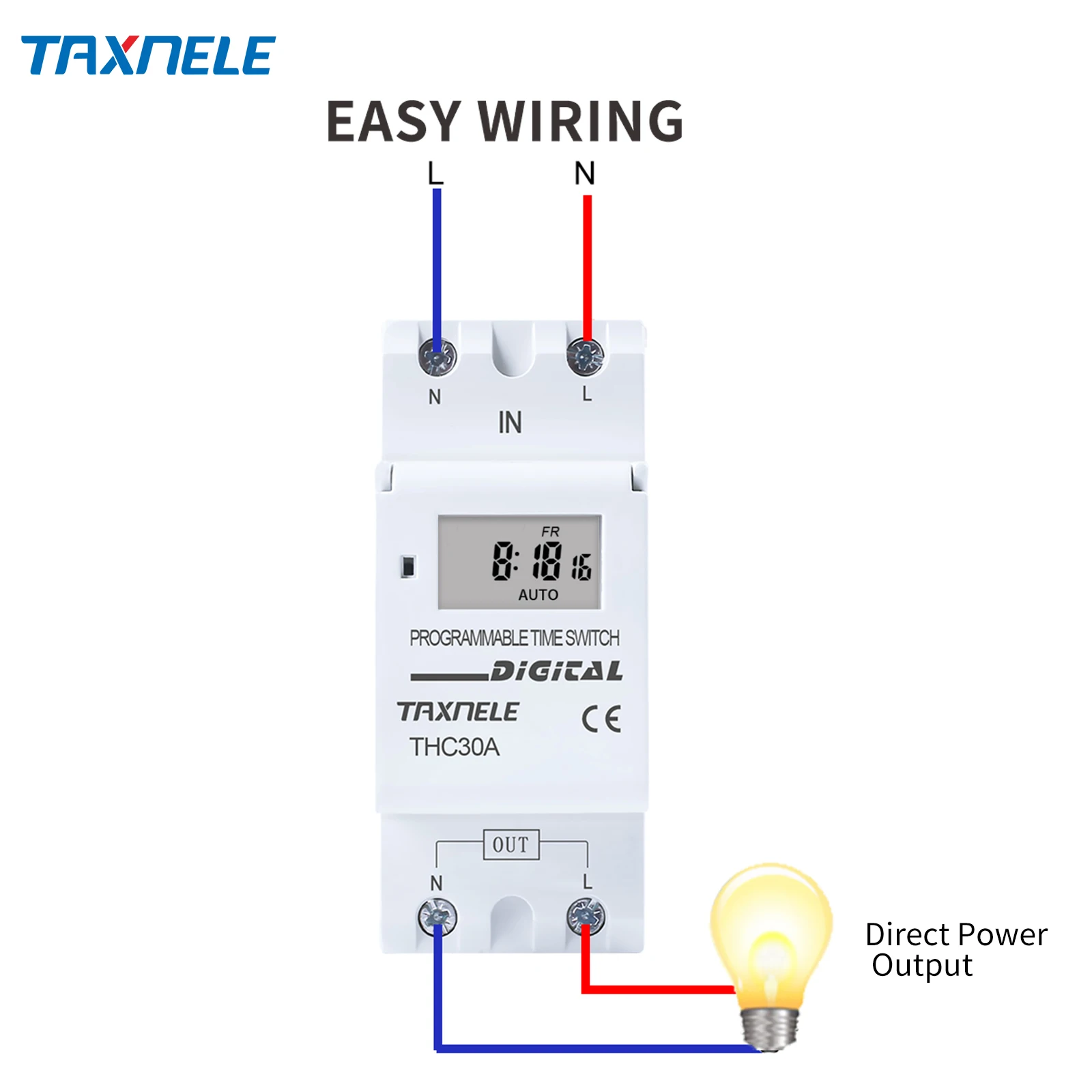

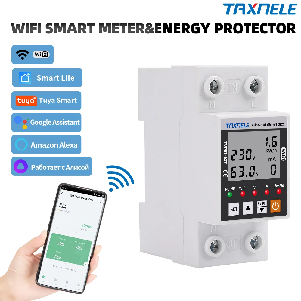
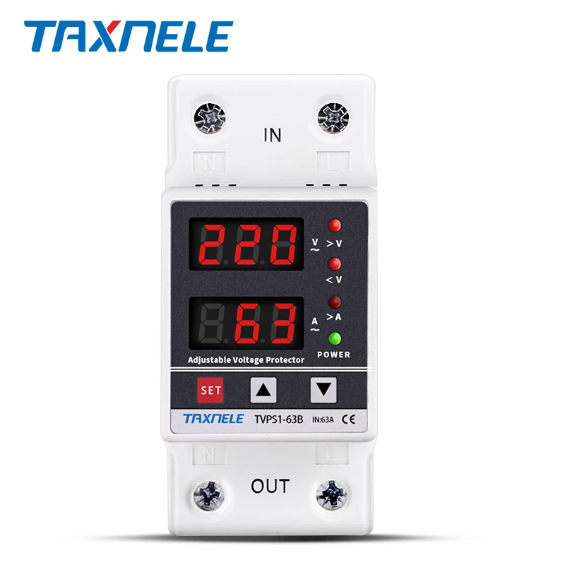
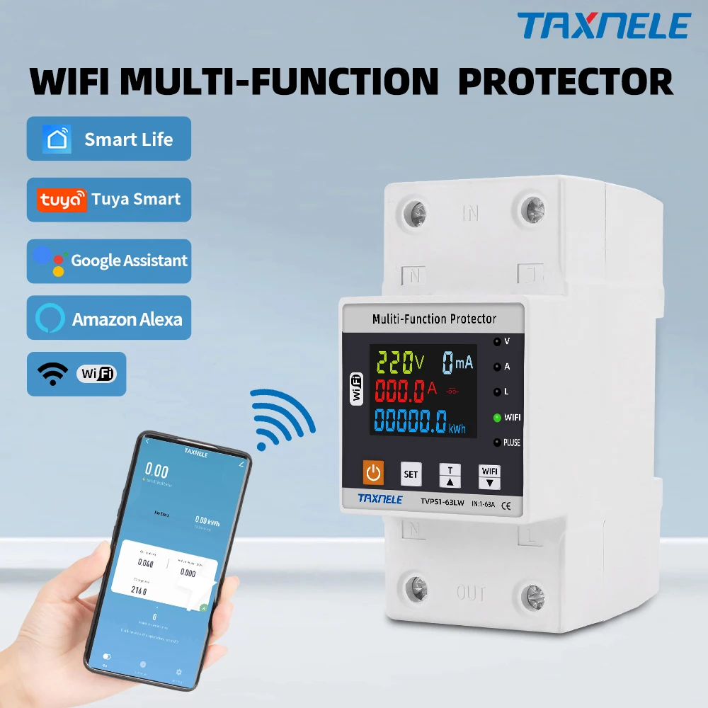
TAXNELE Voltage Relays for Automatic Power Supply Protection
TAXNELE Voltage Relays continuously monitor incoming AC supply voltages and automatically disconnect loads when measurements exceed or fall below preset thresholds, protecting equipment from damage caused by unstable power conditions. These automatic protection relays mount on DIN rail alongside circuit breakers and integrate into residential panels, commercial distribution systems and solar power installations worldwide. Each relay contains precision voltage sensing circuits that measure RMS voltage values and compare them against factory-programmed limits adjustable within industry-standard ranges like 160 to 240 volts for single-phase residential applications. Internal time-delay circuitry prevents nuisance tripping from momentary transients while responding quickly to sustained voltage problems that threaten equipment safety. The relay contact outputs control larger electromagnetic contractors or circuit breaker coils, allowing automatic disconnection of heavy loads without requiring direct switching by the relay itself. Operating temperature range extends from minus 10 to plus 50 degrees Celsius, accommodating both climate-controlled offices and outdoor cabinet installations with temperature variations. TAXNELE relays comply with IEC 60255 standards for electrical measuring and protective relay equipment used across Europe, Asia-Pacific and Americas regions.
Sensing Technology and Relay Control Architecture
Advanced analog-to-digital conversion circuitry samples the AC supply voltage 240 times per second, computing accurate RMS values that reflect true power quality rather than instantaneous peak fluctuations from normal load switching. Programmable hysteresis zones prevent relay chatter by requiring voltage to move a minimum distance beyond the trip threshold before reconnection is permitted, typically 5 to 15 volts depending on application requirements. The relay output contacts switch dry form-A configuration rated for 250 volts AC at 16 amperes, enabling control of contractor coils, indicator lamps and communications signals without additional intermediate switching devices. Single-phase models monitor all three voltage parameters simultaneously on three-phase systems, providing comprehensive protection against phase loss, phase rotation errors and individual phase collapse. Built-in test buttons allow manual verification of relay function during commissioning and periodic maintenance without disconnecting live circuits. Visual status indicators display green during normal operation and red when a trip condition is detected, providing immediate confirmation of protection activation to maintenance personnel. Removable screw terminals accept 0.75 to 2.5 square millimeter copper conductors, simplifying connections within cramped panel environments while maintaining secure contact pressure across thermal cycles.
Advantages Over Fixed Mechanical Protection Methods
Mechanical voltage-sensitive relays cannot adapt to changing supply conditions or building modifications, whereas TAXNELE automatic protection relays adjust to new thresholds in minutes without panel redesign or component replacement. Electronic sensing technology responds to voltage variations with nanosecond precision compared to the hundreds-of-millisecond delays in thermal or mechanical relay designs, substantially reducing the time exposure for sensitive electronics during fault events. Load shedding coordination becomes practical when multiple relays work together, sequentially disconnecting non-critical circuits while maintaining power to emergency systems and essential equipment during extended voltage problems. Independent field testing confirms that facilities protected by TAXNELE relays experience 40 percent fewer unplanned equipment failures compared to installations relying solely on circuit breakers for protection. The investment cost per protected device remains substantially lower than the expense of replacing motor compressors, control boards and precision instrumentation damaged by voltage excursions beyond equipment specifications. Electrical contractors prefer TAXNELE relays because standardized configurations reduce engineering time, simplifying both initial design reviews and future troubleshooting by facility maintenance staff. Browse the complete relay selection at the official TAXNELE store and order online to secure the best available price on automatic protection devices for your specific voltage requirements.
Installation, Configuration and Operational Tips
Mount the relay on DIN rail in positions allowing unobstructed access to the adjustment potentiometer controls, typically located in a dedicated section of the main distribution panel adjacent to the circuit breaker array. Connect the incoming voltage supply to the designated AC input terminals using properly sized conductors based on the measurement source configuration, whether directly from the panel or through current-limiting resistors for high-voltage installations. Adjust the upper voltage threshold first using a precision digital multimeter and a variable AC power supply, recording the exact voltage setting where the relay contact switches from energized to de-energized position. Configure the lower voltage threshold setting by gradually reducing the supply voltage while observing the multimeter and relay output contact state, establishing the minimum acceptable voltage for continued load connection. Test the time-delay function by momentarily reducing supply voltage beyond the lower threshold and confirming that the relay output does not immediately disconnect, verifying that protection allows brief transients while responding to sustained problems. Set the hysteresis zone to approximately 10 percent of the nominal voltage to prevent relay chatter if the supply voltage stabilizes very close to the programmed threshold. Perform quarterly operational verification by manually triggering trip conditions and confirming both visual indicators and load switching response occur within specified parameters.